Operational Tips: Do I Need a Gridded Tube?
What’s a Grid Voltage?
One of the most misunderstood aspects of X-ray tubes is how the electron beam is shaped internally, and what impact that has on the X-ray spot. As a rule of thumb, for spot sizes above approximately 50 microns, the electron beam can generally be passively focused through a combination of emitter geometry and smart electron gun design. For spot sizes below that 50 micron threshold, or for applications where the flux distribution within the spot is important, more active measures must be taken. In this case, tube designers often use a grid voltage which modifies the electrostatic field around the electron beam, causing the electrons to change their trajectory mid-flight.
Depending on the tube designer, these electron beam shaping devices may be called apertures, grids, or focusing optics (not to be confused with external optics which act on the X-ray beam). Depending on the tube design and spot size requirement, one or more focusing optic element may be required to achieve the customer’s required beam size and shape. It’s important to understand that these focusing optics don’t create new electrons or increase the total flux output of the tube in any way. Rather, they simply re-route the electron beam in flight so it lands in a different spot on the X-ray target than it otherwise would.
In the case of a Minifocus tube such as our Seeray, adding a single grid voltage can concentrate the flux into a smaller spot, which can be beneficial in certain applications. For instance, when coupling a Minifocus tube to an external polycapillary X-ray focusing optic, the addition of a single grid voltage inside the tube can help concentrate the available flux in the center of the spot, enabling more efficient use of the optic.
But What Does a Grid Actually Do?
Let’s take the example of a single grid on a Minifocus X-ray tube. The cathode of the tube is ground-referenced, and the anode of the tube is at a high voltage. As electrons are emitted from the tube’s filament, they are effectively at a 0V potential. They “see” the high voltage of on the tube’s anode, and race towards it to equalize the potential difference. The stream of electrons flowing from the cathode to the anode forms the electron beam. Because these electrons are at 0V, we have the ability to shape them as they move towards the anode by manipulating the electrostatic field they fly through with a relatively low grid voltage. Using this principal, MXR is able to design the electrostatic field they pass through in order to manipulate their landing pattern on the target, which forms the X-ray spot.
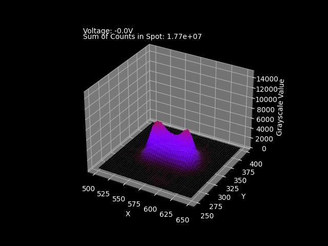
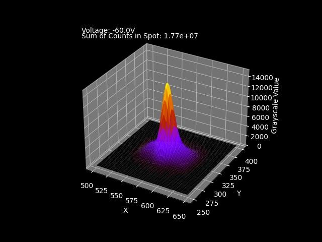
First, let’s look at a visualization of a gridded Minifocus tube’s X-ray spot taken on a production tube at Micro X-Ray, using our pinhole spot photo measurement system with no grid voltage applied. We can distinctly see two lobes in the spot. The total intensity of the spot can be determined by summing the total number of counts in the image, 1.77e7.
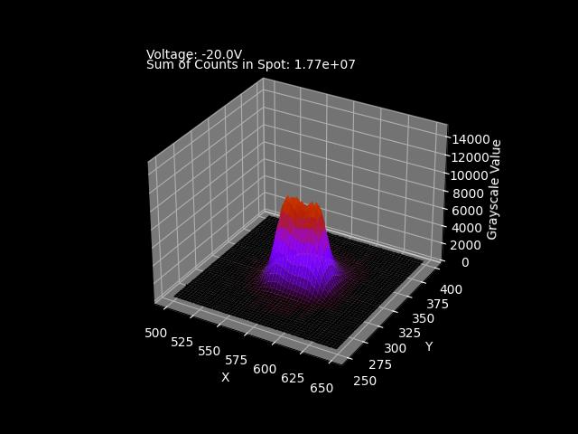
As we increase the electrostatic field strength with a grid voltage of -20V, we can see the two lobes are merging into one as a result of the electrostatic fields acting on the electron beam, but the spot’s sides in the X axis are still quite sloped (these slopes are often called the “wings” of the spot). Note the total counts in the spot area remain unchanged.
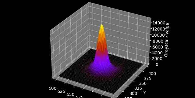
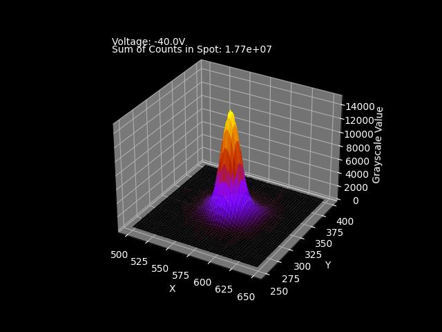
At -40V, the X-ray spot is now a sharp spike, with very steep sides and an intense center. Note the total count rate still remains unchanged, despite a very different shape than the spot with a 0V grid value. We are not adding X-ray flux, we’re simply focusing it in the center of the spot.
And finally, at -60V, we can see the center intensity fall slightly as the wings of the spot increase – this tells us we’ve applied too much voltage to the grid. Again, the total flux intensity remains unchanged, but over focusing the beam results in a less than optimal distribution of the available flux.
Putting It All Together
In the GIF below, we’ve animated the grid voltage changes from 0V through -65V to show the impact of grid voltage on flux distribution. The ideal grid voltage is slightly different for each X-ray tube, and Micro X-Ray will provide you with the optimal grid voltage for your tube.
So what does it mean for you, and do you need a gridded X-ray tube? As always with X-ray tubes, it depends. A gridded tube isn’t better or worse than a non-gridded Minifocus tube, it just depends what your application requirements are. Many analytical applications don’t care about the spot size at all; as long as the cone angle illuminates a larger area than the largest collimator in the system, that’s good enough for the application. However, when high flux intensity in the center of the spot is important, there’s no substitute for a well designed electron beam focusing optic. If you’re using an external polycapillary optic, this increase in flux, combined with the total power of our Seeray X-ray tube can unlock flux intensity previously reserved for sources in the kW range, allowing ultra-fast micro XRF, and even enabling benchtop XRD from a X-ray source running at under 100W!
For More Information on Gridded Tubes
If you have any questions about our gridded tubes, or any tubes at all, please reach out today!

