X-Ray Sources 101: What is Focal Spot Size and Why Does it Matter?

In simple terms, the focal spot size is the size of the electron beam where it hits the target on the tube’s anode. For most analytical applications like XRF, the focal spot size doesn’t really matter (there are always exceptions, of course). As long as the focal spot is “reasonably” small and stable, it is not too important of a spec point. Spot size is a key spec point in any imaging application, so that’s where we’ll focus today.

Spot Size and Resolution

In an imaging application, the focal spot size of the source you’re using is going to be a major factor in the resolution of the image you’ll eventually get out of the source. To understand this, let’s first think of shadows cast in visible light. If you hold an object in front of a normal incandescent bulb, the shadow it creates will have soft edges due to the diffuse surface area of visible light being emitted from the light bulb’s filament. If you hold the same object in front of an LED (say, your phone’s flashlight) the resulting image will have noticeably crisper, sharper edges. This is because the light emitted from the LED is emitted only from the diode’s PN junction and expanding outward from there. In fact, in LEDs this is often a problem as people are adverse to overly-crisp shadows in their homes and offices. As a result, many LEDs incorporate some optical element or opaque plastic in order to diffuse the light to more closely mimic the incandescent style shadows we’re accustomed to.
Now let’s apply the same thinking to X-rays. Unlike photons of visible light, X-ray photons have the ability to penetrate optically opaque materials, so an X-ray image is really just a shadow of the density of the inner components of an object. The same principles that dictate the sharpness of a shadow in visible light hold true in X-rays as well. A smaller X-ray focal spot size correlates to the smaller emission area of an LED, so we can expect sharper, crisper X-ray images with a smaller focal spot size.

Image Quality

There are a few terms to define here that relate to the X-ray image quality:
  • Geometric Unsharpness: The quantitative term for the loss of definition in an image due to focal spot size (and other geometric factors).
  • Penumbra: The partially shaded region on the edge of the shadow in an image.
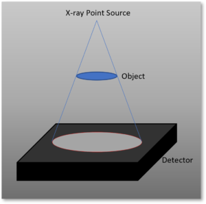
Let’s look at some examples to help clarify these terms. We’ll look at the penumbra generated by an ideal X-say point source, where all X-rays are generated in the exact same space. Then we’ll look at the X-rays generated by a focal spot of a Microfocus tube with an X-ray spot of 5μm.
x-ray point source

X-ray coverage on a detector shown with a X-ray point source
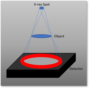
In this first image, the X-rays are emitted from an ideal point source. In this case, the penumbra (illustrated by the thin red line on the edge of the X-ray image on the detector) is nearly nonexistent.
x-ray spot source

X-ray coverage on a detector shown with a X-ray spot of some quantifiable size

In this second image, the X-rays are generated in a focal spot with some real diameter, not an ideal point source. In this case, we can see the penumbra is quite a bit larger than with the point source. This is due to the fact that X-rays from all areas of the spot are hitting the edge of the object at slightly different angles, causing partial shading in the detector image.
Armed with this information, we can see that the highest resolution object you can image, therefore, will be dictated by the size of the spot.

What does this mean in practice?

When selecting a spot size, the amount of geometric unsharpness that you can tolerate depends on the size of the feature you’re measuring and the size of the penumbra.


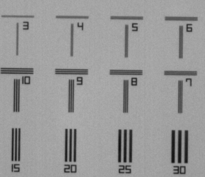
Line Pair Gauge

X-ray image of a line pair resolution gauge, with line pairs from 3 – 30 microns.

The above image is of an X-ray of a line pair gauge, taken with a Microbox with a 5μm focal spot size. The line pairs are a high density material on a low density substrate. Each grouping is a set of three lines of a certain width, spaced the same width apart. This gives us a easy, repeatable way to measure the size of resolvable details using any given X-ray source.

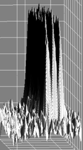
3D visualization of 5µm line pairs

Visualization of 5µm line pairs with the grey value assigned to the Z axis.

If we now zoom in on the 5µm line pair and apply a 3D visualization by assigning the grey value to the Z axis, we can easily resolve the three distinct peaks by eye; one peak for each of the three 5um width lines on the gauge. However, notice the pyramidal shape and how the features tend to blur together at the base of the shape. This is the penumbra from the 5μm spot causing geometric unsharpness that’s blurring the image, and because the lines and spaces are themselves only 5μm, we are nearing the minimum resolvable feature size of this source. Whether or not this resolution is good enough is a choice for the system designer to make.

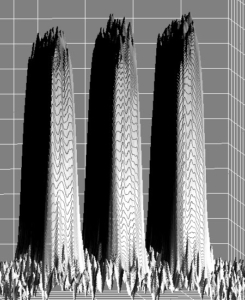
30µm line pair

Visualization of 30µm line pairs with the grey value assigned to the Z axis.

Next, we’ll zoom in on the 30µm pair from the same line pair image, and apply the same 3D visualization. In this case we can see a distinct tabletop shape to the lines, with a clear valley between them. This is because the penumbra from a 5µm spot will only blur the outer 5µm of the lines. Because the lines are 30µm wide and the space between them is 30µm wide, the line pairs are clearly resolvable and can easily be distinguished.


What size spot do you need?

As with everything in X-rays, it depends. If your application is an online QC process on canned food and you need to see things like bone fragments left in processed meats, you generally won’t need to see anything less than about 500μm. If you’re looking at bond wires inside an integrated circuit package, you may need to see if a 12μm bond wire is intact and correctly spot welded to the die. Spot size, feature size, magnification, and more all play a part in determining the ideal spot size for any application.
Because X-ray sources tend to increase in complexity (and cost) as the spot size decreases, it is important to understand the minimum size object you need to resolve, and work backwards from there to identify the correct X-ray source. The MXR support team is always available to help guide these conversations to the best tube for your application.

Other factors affecting resolution

Of course, the detector is going to play a large part in this as well. A flat panel detector behaves differently than an image intensifier. An energy discriminating detector is going to not only give you a photon count, but also a photon energy reading. A detector with a 100um pixel pitch might work for some high magnification applications, but render your image completely useless in other applications.
In addition to the spot size and the detector used, careful attention must be paid to the geometry of the system, the cone angle of the tube, and the mechanical stability of the system. In some systems, a tiny vibration from, say, an automated stage will render your images useless for a CT reconstruction algorithm, but will be perfectly acceptable for a 2D fluoroscopy application.

Let’s Talk!

Contact us today to talk about your imaging application, our Microbox source which is purpose-built for X-ray imaging, or anything else X-ray related!